

close
Choose Your Site
Global
Social Media


Views: 0 Author: Site Editor Publish Time: 2026-09-07 Origin: Site


Compressed air leaks and pressure drops carry a massive quantifiable penalty in industrial automation. Energy waste escalates rapidly when systems lose pressure, forcing compressors to run continuously. Compressor wear accelerates as equipment works harder to maintain baseline output. Specifying incorrect connection types directly leads to premature component failure. It causes unplanned maintenance downtime and introduces severe safety hazards on the factory floor. This guide provides a technical framework for evaluating and selecting pneumatic fittings. You will learn how to standardize your pneumatic components based on pressure ratings and environmental conditions. We focus on engineering realities rather than assumptions. You will understand how to match specific connection mechanisms to your operational demands. Proper selection ensures system reliability, prevents dangerous blowouts, and maximizes long-term equipment uptime across your entire facility.
Application Dictates Connection: Push-to-connect fittings maximize assembly speed, while compression and semi-fast fittings are mandatory for high-vibration or high-pressure environments.
Material Compatibility is Non-Negotiable: Selecting between brass, stainless steel, and composites requires analyzing the operating environment (e.g., washdown, chemical exposure, extreme temperatures).
Standardization Prevents Catastrophe: Mixing thread standards (NPT, BSPT, Metric) or mismatched tubing tolerances is the leading cause of blowouts and thread galling.
Selecting the right components requires a strict evaluation of your system parameters. Guesswork leads to catastrophic blowouts or chronic micro-leaks. You must define the exact mechanical and environmental stresses your system will endure before ordering parts. We see facilities constantly replacing blown lines because they failed to calculate baseline operational metrics.
You must calculate the required pressure ratings for your entire system. Do not rely solely on the nominal operating pressure. Systems experience sudden pressure spikes during valve actuation or emergency stops. Factor in a safety margin of at least 2.5 times the maximum working pressure. This burst margin prevents catastrophic failure when regulators malfunction. Always verify that both the fitting and the tubing share compatible pressure thresholds. A high-pressure brass body means nothing if you pair it with thin-walled polyurethane tubing that ruptures at 120 PSI.
Internal fitting geometry directly impacts air volume delivery. Every angle and reduction in internal diameter creates flow resistance. This resistance causes a pressure drop across the connection. High pressure drops starve pneumatic actuators of necessary air volume. This starvation slows down actuator response times and reduces cylinder force. Select components with smooth internal transitions and maximize the inner diameter wherever space permits. When designing high-speed sorting machinery, even a 5 PSI drop across a manifold significantly alters machine timing.
Internal Geometry | Flow Restriction Level | Impact on Actuator Speed |
|---|---|---|
Straight Through (Full Bore) | Minimal | Maintains maximum design speed |
Standard 90-Degree Elbow | Moderate | Slight reduction in cycle times |
Banjo Style (Restricted Bore) | High | Noticeable lag in cylinder extension |
Continuous machine movement dictates the required mechanical grip of your connections. High-vibration environments slowly back out threaded connections and degrade O-ring seals. Instant connections might fail if hoses whip violently during operation. You must evaluate the frequency and amplitude of machine vibrations. Rigid piping requires different mechanical securing methods than flexible robotic arms. Stamping presses and vibratory bowl feeders destroy standard push-in connections within weeks, requiring mechanical compression alternatives.
Sensitive environments require strict compliance with industry standards. You must evaluate FDA, 3-A, or ISO cleanroom compliance before specifying components. Food processing demands crevice-free designs that prevent bacterial growth. Cleanrooms require materials that do not outgas or shed particulates. Washdown environments need components capable of withstanding high-pressure caustic chemical sprays without degrading. Standard nickel-plated brass strips away rapidly when exposed to industrial bleach solutions.
No single connection type works for every application. You must balance assembly speed, mechanical security, and spatial constraints. Understanding the internal mechanics of each type allows you to make informed engineering decisions on the shop floor.
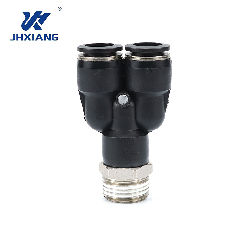
These units utilize an internal stainless steel collet and an O-ring sealing design. When you insert the tubing, the collet's teeth bite into the exterior wall. The O-ring creates an immediate airtight seal around the tube's circumference. They are best for rapid assembly and disassembly. You will find them heavily utilized in standard factory automation and confined spaces. They eliminate the need for wrenches during installation.
Their primary limitation is susceptibility to leaks under certain conditions. If the tubing is side-loaded, scratched, or cut at an angle, the O-ring cannot seal properly. They also possess a lower vibration tolerance compared to mechanical compression alternatives. We recommend them strictly for static lines or smooth-motion actuators.
Compression designs use a metal or plastic ferrule. You slide the nut and ferrule over the tubing. Tightening the nut compresses the ferrule permanently onto the tubing wall. This creates an incredibly robust mechanical grip. These are best for high-pressure applications and semi-permanent installations. They excel in rigid piping networks where vibration is present but disconnection is rarely required.
The main limitation is the slower assembly time. Installation requires wrenches and physical clearance to turn the tools. Once compressed, you often must cut the tubing to replace the connection. You must also ensure you do not over-tighten the nut, which can crush the tubing and restrict internal airflow.
This hybrid design features a barbed stem and a knurled locking nut. You push the flexible tubing over the barb. You then thread the locking nut over the tubing, clamping it securely against the barb. They are best for applications requiring higher pull-out resistance than instant fittings. They offer faster assembly than standard compression fittings. They bridge the gap between speed and mechanical security.
Limitations include the need for manual tightening. Operators can under-tighten or over-tighten the nut. They are also limited to specific flexible tubing types, like soft polyurethane. Rigid nylon tubing will not stretch over the barb profile.
These mechanisms feature a spring-loaded sleeve and a ball-latch system. Pulling the sleeve back retracts the locking balls, allowing you to insert or remove the plug. Internal valves automatically shut off airflow when disconnected. They are best for modular machine sections and pneumatic tools. They serve as frequent changeover points requiring zero-pressure disconnect safety features. They allow operators to swap tools without venting the entire main line.
Limitations include a bulkier physical profile. They introduce a higher potential for increased pressure drop across the internal valve mechanism. They also require a larger initial space envelope on the manifold.
Barbed profiles rely on an interference fit. The barb stretches the tubing outward. External hose clamps or crimped ferrules provide the final mechanical securing force. They are best for highly flexible tubing like silicone or soft polyurethane. They are heavily used in low-pressure applications and fluid transfer lines.
They are notoriously difficult to disassemble without cutting the hose. There is also a high potential for hose degradation at the exact point where the clamp bites into the material. Over-tightening a worm-gear clamp will slice right through soft silicone lines.
Bulkhead designs allow you to pass air lines safely through control panels or machine enclosures. They feature a long threaded body and locking nuts on both sides of the panel. When evaluating these, focus heavily on panel thickness limits. You must also consider environmental sealing at the pass-through point. Specify appropriate IP ratings to prevent dust or moisture ingress into electrical cabinets.
These specific components connect air lines directly to pneumatic actuators. A cylinder joint connector must handle dynamic motion. They often incorporate swivel capabilities to manage movement. When evaluating them, discuss articulation and alignment compensation. Proper swivel action prevents side-load stress on the cylinder port. This prevents premature wear on both the tubing and the actuator seals.
The material of your components dictates their lifespan in harsh environments. Selecting the wrong material guarantees rapid corrosion or mechanical failure. You must match the metallurgy or polymer to the specific ambient conditions on your factory floor.
Material Type | Corrosion Resistance | Mechanical Strength | Ideal Application Environment |
|---|---|---|---|
Nickel-Plated Brass | Moderate | High | Dry indoor manufacturing, packaging |
Stainless Steel (316) | Exceptional | Very High | Chemical washdown, food processing |
Engineered Composites | High (Chemical Specific) | Moderate | Robotics, semiconductor cleanrooms |
This material serves as the industry standard for a reliable industrial air connector. The brass core provides high mechanical strength and excellent machinability. The nickel plating offers moderate corrosion resistance against ambient moisture. Use cases include general manufacturing, automotive assembly, and packaging machinery. They perform exceptionally well in dry, indoor environments where extreme chemicals are absent.
Stainless steel delivers high chemical resistance and extreme temperature tolerance. Type 316 provides superior resistance to chlorides and harsh cleaning agents. It is easily sanitized and resists pitting. Metric sanitary fittings utilize specific crevice-free designs. Tri-Clamp compatibility is strictly required for FDA and 3-A compliance in aggressive washdown environments. Primary use cases include food and beverage processing and pharmaceutical manufacturing. They are mandatory in corrosive chemical environments where brass would rapidly degrade.
Engineered plastics like PBT or POM offer a lightweight alternative to metals. They are highly resistant to specific chemicals that might attack brass. They do not suffer from galvanic corrosion. Use cases include end-of-arm tooling in robotics where weight reduction is critical. They are also common in semiconductor manufacturing and low-pressure pneumatic logic circuits.
Thread incompatibility destroys components and causes massive air leaks. You must understand the distinct thread geometries used globally. Forcing mismatched threads together ruins the equipment permanently and creates dangerous projectiles under pressure.
NPT (National Pipe Thread) is the standard in North America. It features tapered threads that seal by wedging together. BSPT (British Standard Pipe Taper) also uses tapered threads but has a different thread angle (55 degrees vs. NPT's 60 degrees). They are completely incompatible. BSPP (British Standard Pipe Parallel) uses straight threads. It does not seal on the threads themselves. Metric threads are also parallel and rely on exact pitch measurements. You cannot mix these standards under any circumstances.
Tapered threads require a sealant to fill the microscopic gaps between the metal crests and roots. Many modern components feature pre-applied thread sealants. Alternatively, technicians apply PTFE tape during installation. When applying PTFE tape, wrap it in the direction of the threads, using no more than three wraps. Parallel threads require a captive O-ring or a bonded seal washer. The seal occurs at the base of the thread against a flat machined face. These provide a highly reliable seal without the risk of tape fragments entering the air stream.
Forcing incompatible threads causes severe mechanical and safety consequences. It shears the metal threads, creating debris that travels into sensitive valves. The connection will inevitably blow out under pressure. Mixing metals, such as threading a brass component into an aluminum manifold without proper sealant, introduces galvanic corrosion. Over time, the metals fuse together, making future maintenance impossible without destroying the manifold.
Accurate sizing prevents leaks and tube blowouts. You must measure correctly and match the tubing material to the connection mechanism. A pneumatic tube connector only functions when paired with exact tubing specifications.
You must understand the critical distinction between Outer Diameter (OD) and Inner Diameter (ID). Push-to-connect systems grip the outside of the tube. Therefore, you must specify the exact OD. A 6mm OD tube requires a 6mm OD receptacle. Barbed systems insert into the tube. Therefore, you must specify the exact ID. Using OD measurements for barbed connections guarantees a loose, leaking fit.
The durometer of the tubing dictates how well the mechanism grips and seals. Nylon tubing is rigid and handles high pressure well. It works perfectly with push-in and compression systems. Polyurethane is highly flexible and kink-resistant. However, very soft polyurethane might collapse inside a push-in mechanism under pressure. PTFE tubing offers unmatched chemical resistance but has a slippery surface that challenges some instant gripping collets.
High-pressure systems require specific wall thicknesses. If the wall is too thin, the tube will collapse inward when the collet attempts to grip it. This collapse breaks the O-ring seal and causes a blowout. Always cross-reference the manufacturer's minimum wall thickness requirements for your specific operating pressure.
Even the best components fail if installed incorrectly. Operator error during assembly accounts for the vast majority of system leaks. Implement strict assembly protocols to protect your system.
Angled cuts or jagged burrs on the end of the tubing act like razor blades. When you insert a poorly cut tube, it slices the internal O-ring. This creates an immediate, unfixable micro-leak.
Mandate the use of dedicated tube cutters.
Never allow technicians to use utility knives or side-cutters.
Inspect the tube end to ensure a perfectly square, burr-free profile before insertion.
Routing tubes too tightly pulls the tube away from the internal sealing mechanism. This side-loading creates an asymmetrical gap at the O-ring. It also stresses the collet teeth on one side, leading to eventual mechanical failure.
Implement 90-degree elbow components to navigate tight corners.
Adhere strictly to the tubing manufacturer's minimum bend radius specifications.
Use tubing clips to support long runs and prevent sagging.
Dust, metal shavings, or debris entering the system during assembly causes severe damage. Debris prevents O-rings from seating properly and destroys downstream valve spools.
Establish clean-assembly protocols on the shop floor.
Keep all components in sealed bags until the exact moment of installation.
Use protective plastic caps on all open ports during the machine build phases.
Blow out all lines with clean, dry air before final connection to actuators.
Take the following actionable steps to improve your system reliability:
Audit existing pneumatic circuits for mismatched thread types and replace any temporary adapters with permanent solutions.
Standardize facility procurement on a single thread standard to eliminate cross-threading risks during maintenance shifts.
Implement mandatory tube-cutter training for all assembly technicians to eliminate O-ring damage from jagged cuts.
Specify stainless steel components for all washdown zones and verify 3-A compliance documentation with your supplier.
A: Hydraulic components handle heavy fluids at extreme pressures, often exceeding 3,000 PSI. They rely on heavy steel construction and metal-to-metal sealing faces. Pneumatic components handle compressed gases at much lower pressures, typically under 150 PSI. They utilize lighter materials like brass or plastic and rely on O-rings or thread sealants for airtight integrity.
A: You must use precise tools. Use a thread pitch gauge to determine the exact distance between thread crests. This identifies if the thread is NPT, BSPT, or Metric. Use digital calipers to measure the major diameter of the threads. Use the calipers to measure the exact Outer Diameter (OD) or Inner Diameter (ID) of the tubing receptacle.
A: Yes, but with strict limitations. Every time you insert and remove the tubing, the internal stainless steel grab ring wears down slightly. The internal O-ring also degrades over multiple cycles. While they are reusable for occasional maintenance, do not use them in applications requiring daily connection and disconnection.
A: Leaks typically stem from severe vibration loosening the threaded base. Side-loading is another major cause; if the tubing pulls the swivel joint at a harsh angle, it deforms the internal seals. Worn internal O-rings from millions of articulation cycles will also eventually cause air to bypass the seal.
A: Compression designs provide the highest security against vibration. Semi-fast nut-locked designs also perform exceptionally well. For extreme environments, specify all-metal designs rather than plastic bodies. Avoid standard instant push-in designs, as constant vibration can cause the internal collet to slowly release its grip on the tubing.
A: Absolutely not. Mixing metric tubing with imperial receptacles creates a catastrophic mismatch. Even if they seem close in size, the slight tolerance difference prevents the O-ring from sealing properly. This mismatch guarantees blowouts under pressure. You must mandate exact matching across your entire system.
A: Yes, manufacturers use color coding for rapid identification. Often, a blue or green ring indicates metric sizing, while a red or grey ring indicates imperial sizing. Some manufacturers use specific colors to denote high-pressure ratings or specific internal seal materials. Always check the specific manufacturer catalog for their exact color legend.


