

close
Choose Your Site
Global
Social Media


Views: 0 Author: Site Editor Publish Time: 2026-08-31 Origin: Site


Incorrect fitting selection drains maintenance budgets rapidly. Minor sizing mismatches create system leaks, and pressure drops follow immediately. Unplanned downtime halts automated environments. Navigating competing measurement standards complicates routine maintenance on the plant floor. You face Imperial versus Metric dimensions daily. You encounter NPT, BSPT, and BSPP thread types on the same manifold. Replacing components on imported or legacy machinery often involves pure guesswork. We designed this guide to solve these exact problems. Below, you will find a comprehensive size chart and true-to-size visual identification tools. We also provide an evaluation framework to standardize your component procurement. This approach eliminates guesswork, standardizes your inventory, and ensures reliable connections across your entire compressed air infrastructure.
Match Tubing OD to Fitting Size: Pneumatic push-to-connect fittings are universally sized by the Outer Diameter (OD) of the tubing, not the Inside Diameter (ID).
Verify Thread Standards Before Ordering: Mixing NPT (tapered) and BSPP (parallel) threads is a primary cause of catastrophic thread failure and system leaks; precise identification is non-negotiable.
Tubing Material Dictates Connection Style: The durometer (hardness) of your tubing, hose, or pipe (e.g., Polyurethane vs. Nylon) directly impacts whether a push-to-connect or compression fitting will hold under pressure.
Material Dictates Reliability: While composite fittings suit standard air lines, high-temperature or high-vibration environments require robust materials like a brass pneumatic fitting to maintain integrity.
Standardize for Scalability: Consolidating fitting types and thread standards across a facility reduces MRO inventory costs and minimizes maintenance errors during retrofitting.
Modern air systems rely heavily on push-to-connect technology. These components grip and seal based entirely on the tubing's Outer Diameter (OD). Measuring the Inside Diameter (ID) leads to incorrect component selection. You must measure the outside wall. Imperial tubing is measured in fractions of an inch. Metric tubing is measured in millimeters. Mixing these up causes immediate blowouts on the production line.
Certain sizes appear similar but are not strictly interchangeable. However, specific cross-over points exist in modern manufacturing. For example, 5/32" tubing measures approximately 3.96mm. Many manufacturers design their 4mm push-to-connect ports to accept 5/32" tubing without leaking. Conversely, 5/16" tubing equals 7.93mm, which often fits securely into an 8mm port. You should never attempt to mix 1/4" (6.35mm) tubing with a 6mm port. The size gap is too large, and the internal O-ring will fail to engage the tube wall.
Tubing tolerance plays a massive role in connection success. High-quality pneumatic tubing maintains a strict OD tolerance, usually within +/- 0.004 inches. If tubing falls outside this tolerance due to poor manufacturing or excessive wear, the internal O-ring cannot compress properly. Air escapes past the seal. Always verify that your tubing meets the dimensional tolerances specified by the manufacturer of your pneumatic fittings.
Imperial Tubing OD | Metric Equivalent (mm) | Closest Metric Standard | Interchangeability Status |
|---|---|---|---|
1/8" | 3.175 mm | 3 mm | Do Not Mix |
5/32" | 3.968 mm | 4 mm | Often Interchangeable |
1/4" | 6.350 mm | 6 mm | Do Not Mix |
5/16" | 7.937 mm | 8 mm | Often Interchangeable |
3/8" | 9.525 mm | 10 mm | Do Not Mix |
1/2" | 12.700 mm | 12 mm | Do Not Mix |
Thread standards cause the most confusion on the plant floor. National Pipe Taper (NPT) is the standard in North America. The threads taper at a 60-degree angle. They form a mechanical seal by wedging together. British Standard Pipe Taper (BSPT) is common in Asia and Europe. BSPT threads taper at a 55-degree angle. British Standard Pipe Parallel (BSPP) features straight threads. BSPP requires a bonded seal washer or an O-ring to prevent leaks. Forcing an NPT male into a BSPT female port strips the threads and guarantees a leak.
Nominal thread sizes do not match actual measured diameters. A 1/4" NPT thread does not measure 1/4" across. It measures closer to half an inch. Use the reference table below to map nominal sizes to actual measured outside diameters.
Nominal Thread Size | Threads Per Inch (NPT) | NPT Actual OD (inches) | NPT Actual OD (mm) | BSPT/BSPP Actual OD (mm) |
|---|---|---|---|---|
1/8" | 27 | 0.405" | 10.29 mm | 9.73 mm |
1/4" | 18 | 0.540" | 13.72 mm | 13.16 mm |
3/8" | 18 | 0.675" | 17.15 mm | 16.66 mm |
1/2" | 14 | 0.840" | 21.34 mm | 20.96 mm |
3/4" | 14 | 1.050" | 26.67 mm | 26.44 mm |
1" | 11.5 | 1.315" | 33.40 mm | 33.25 mm |
Digital measurements sometimes leave room for doubt. A 1:1 scale printable template offers a physical overlay solution. Maintenance teams print a true-to-size guide on standard paper. You must ensure your printer scaling is set to 100% and disable any "fit to page" settings. Once printed, physically place existing plugs, couplers, and male threads directly onto the paper. This allows you to match thread profiles and tubing diameters against the printed outlines. Visual identification speeds up the replacement process during urgent machine breakdowns. Watch out for parallax error; look directly down over the component rather than from an angle to ensure the printed lines match the physical threads.
Retrofitting older machines requires a systematic approach. Guessing leads to stripped manifolds and extended downtime. Follow a strict measurement protocol to identify unknown ports.
Determine the gender of the connection. Male threads sit on the outside of the component. Female threads reside on the inside of the port.
Grab a digital caliper. Measure the outside diameter of the male thread across its widest point (the peaks). Compare this measurement to the thread sizing chart.
Identify the pitch using a thread pitch gauge. Press the toothed blades of the gauge against the threads until you find a perfect match. NPT threads are measured in threads per inch (TPI). Metric threads are measured by the distance between individual thread peaks in millimeters.
Check for taper. Place a straight edge against the threads. If the threads angle inward toward the tip, it is a tapered thread (NPT or BSPT). If they remain perfectly flat, it is a parallel thread (BSPP or Metric).
Imported equipment often requires you to decode obscure standards. Japanese Industrial Standard (JIS) threads frequently appear on machinery from Asia. JIS tapered threads are functionally identical to BSPT. However, DIN standards from Germany might use metric parallel threads (M-series). These mimic standard imperial sizes but will cross-thread immediately if forced. Always measure twice before ordering replacement parts for imported machinery.
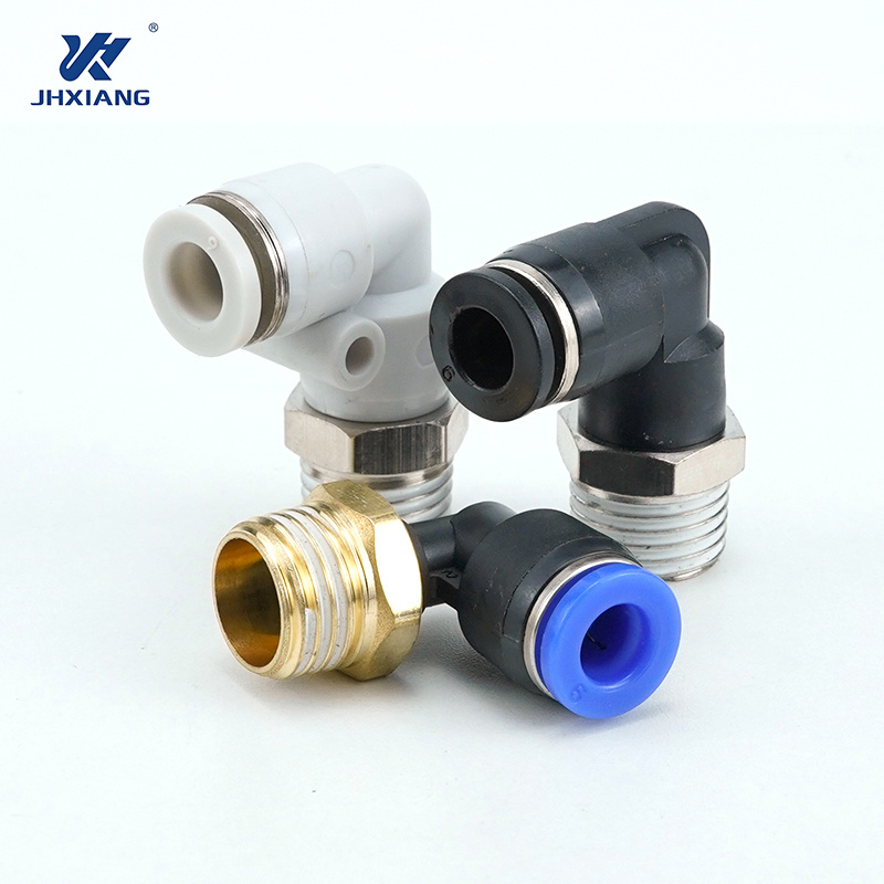
You must choose between push-to-connect and compression styles based on your operational outcomes. Push-to-connect designs dominate modern automation. They allow for rapid assembly and disassembly without tools. You simply push the tubing past the internal collet and O-ring. They handle standard shop air pressures well. However, they rely entirely on the tubing's structural integrity to maintain the seal.
Compression fittings require a nut and a ferrule. You slide the nut and ferrule over the tubing, insert it into the body, and tighten the nut with a wrench. This creates a permanent or semi-permanent mechanical grip. Compression styles tolerate much higher pressures and aggressive mechanical vibrations. The trade-off is installation speed. Assembly takes longer. Disassembly often requires cutting the tubing to remove the deformed ferrule.
Connection Style | Installation Speed | Vibration Resistance | Best Application |
|---|---|---|---|
Push-to-Connect | Very Fast (Tool-free) | Moderate | Factory automation, robotics, standard air lines |
Compression | Slow (Requires wrenches) | High | High-vibration machinery, permanent installations |
Barbed | Moderate (Requires clamps) | Low to Moderate | Low-pressure fluid transfer, flexible hoses |
Your tubing material dictates your fitting choices. Polyurethane is highly flexible and resists kinking. It works well in tight spaces. However, it is soft. Under high pressure or side-load stress, soft polyurethane deforms inside a push-to-connect collet, leading to leaks. Nylon tubing is much more rigid. It holds its shape perfectly, making it the ideal partner for standard push-to-connect systems.
PTFE (Teflon) tubing handles extreme chemicals and high temperatures. Polyethylene offers a low-cost solution for low-pressure fluid transfer. When using very soft tubing with mechanical grips, you often need an internal tube support. You insert this small metal or plastic sleeve into the end of the tubing before assembly. The insert prevents the tube wall from collapsing inward when the external collet or ferrule bites down.
Air tool connections introduce another layer of complexity. Standard in-line components join tubing to valves or cylinders permanently. Quick disconnect couplers allow operators to swap air tools rapidly. You must match the plug profile (the male end on the tool) to the coupler body (the female end on the hose).
Three main profiles dominate the market. The Industrial profile (Type D) features a distinct wide ring. The Automotive profile (Type C) has a narrower profile. The ARO profile features a longer, tapered nose. Mismatching these profiles is a common mistake. An Industrial plug might physically click into an Automotive coupler, but it will leak massive amounts of air. Always standardize your entire facility on a single quick-disconnect profile.
Standard plastic or composite bodies handle the majority of basic factory automation tasks. They are lightweight, cost-effective, and resist mild corrosion. However, they fail rapidly in harsh environments. High ambient heat, welding spatter, and aggressive washdown chemicals melt or degrade composite plastics.
For these severe applications, you need a brass pneumatic fitting. Brass withstands high temperatures and resists damage from physical impacts. In automotive manufacturing or heavy metal fabrication, hot sparks easily destroy plastic release collars. Brass components shrug off these hazards and keep the lines pressurized.
When system integrity is critical, engineers specify a zero-leakage brass push fitting. These utilize all-metal internal collets rather than plastic grip rings. They also incorporate high-grade FKM or Viton O-rings instead of standard NBR (Nitrile). FKM resists synthetic compressor oils and extreme heat. This engineering prevents catastrophic seal failure in aggressive industrial settings.
Internal geometry restricts air flow. Every component you add to a circuit creates a minor bottleneck. This flow capacity is measured by the coefficient of flow (Cv). A higher Cv indicates greater air volume passing through the port at a given pressure. Right-angle elbows have a lower Cv than straight connectors because the air must abruptly change direction.
You must calculate acceptable pressure drops across complex manifolds. If you chain too many restrictive components together, the end-of-line actuators will starve for air. They will actuate slowly or fail to generate adequate force. Size your supply lines larger than your branch lines. Use components with smooth internal transitions to maximize Cv and ensure system scalability.
Machine design dictates your routing strategy. Straight connectors offer the best flow rates and take up minimal lateral space. You use them when tubing can run directly away from the port. Elbows solve tight clearance issues. Fixed elbows require you to thread the body until tight, which might leave the tubing port facing the wrong direction. Swivel elbows solve this problem. You tighten the threaded base, and the upper body rotates 360 degrees to align with your tubing path.
Y-fittings allow you to split a single line into two parallel lines. You must respect the bend radius limitations of your pneumatic tubing. Forcing rigid nylon tubing into a tight 90-degree turn without an elbow creates side-load stress. This stress pulls the tubing away from the internal O-ring, creating a persistent micro-leak.
Splitting air supply to multiple actuators requires structural stability. Using an industrial pneumatic tee fitting provides a robust branching solution. Tee configurations allow a main supply line to enter one port and branch off at a 90-degree angle while continuing straight to another zone.
You must evaluate flow distribution when using tees. Symmetrical distribution occurs when air enters the center leg and splits evenly to the left and right. Asymmetrical distribution happens when air enters one side and flows straight across, with only a portion diverting down the center leg. Asymmetrical setups cause uneven cylinder actuation times if the downstream volume demands are high. Plan your tee placements to ensure balanced air delivery across the manifold.
Tapered threads (NPT and BSPT) require a sealant to fill the microscopic gaps between the metal peaks and valleys. Manual PTFE tape is common but risky. If applied incorrectly, shreds of tape break off and travel downstream. These shreds clog sensitive directional control valves and ruin expensive actuators. Always wrap tape clockwise, starting one thread back from the end.
Pre-applied PTFE thread sealants eliminate this risk. Manufacturers coat the threads with a dry sealant compound at the factory. When you thread the component into the port, the compound activates and seals the gaps perfectly. This prevents system contamination and drastically speeds up assembly time on the production floor.
Sealant Type | Application Method | Contamination Risk | Best Use Case |
|---|---|---|---|
PTFE Tape | Manual wrap (clockwise) | High (if applied poorly) | Field repairs, low-budget installations |
Liquid Sealant | Manual drop on threads | Moderate | Permanent installations, large pipe threads |
Pre-Applied Sealant | Factory coated | Very Low | High-volume manufacturing, rapid assembly |
Thread galling occurs when friction and pressure cause two metal surfaces to cold-weld together. This happens frequently when mating identical materials, such as a stainless steel male thread into a stainless steel female port. Once galled, the threads lock up permanently. You will destroy the component trying to remove it.
Mitigate galling by using proper lubrication. Anti-seize compounds or nickel-infused PTFE tape provide a barrier between the metal surfaces. Cross-threading is a different risk. It happens when you force mismatched threads together, or start a thread at an angle. Always start threads by hand for the first two full turns. If you feel immediate heavy resistance, stop. Back it out and check your thread pitch compatibility.
Cumulative pressure drops cripple automated machinery. Using too many right-angle elbows in a single circuit restricts flow severely. Replace unnecessary elbows with sweeping tube bends where space allows.
Micro-leaks often stem from poor tubing preparation. If you cut tubing with scissors or a knife, the end becomes oval-shaped or angled. An angled cut prevents the tubing from seating fully against the internal stop. Deep scratches on the outside of the tubing provide a path for air to bypass the O-ring. Always use a dedicated tube cutter to ensure perfectly square, clean cuts. If a tube is scratched, cut off the damaged section before inserting it into a push-to-connect port.
Allowing mixed metric and imperial systems on the plant floor creates chaos. Maintenance technicians waste hours searching for the correct adapter. They often force a 1/4" tube into a 6mm port out of desperation, causing leaks.
Standardizing all pneumatic ports to a single thread type (e.g., NPT) and a single tubing standard (e.g., Imperial) carries an upfront cost. You must replace existing mismatched components. However, the long-term operational benefits heavily favor standardization. It reduces your MRO inventory requirements. It eliminates cross-threading risks. It ensures your maintenance team can execute rapid, leak-free repairs during critical production runs.
Measure the tubing OD and verify the port thread type using a caliper and pitch gauge before ordering replacements.
Audit your current MRO inventory to identify and remove mismatched thread standards.
Standardize your facility's quick-disconnect profiles to a single type to prevent air loss at the tool end.
Contact engineering support for samples of high-performance brass components for evaluation in your harshest environments.
A: Use digital calipers to measure the exact Outer Diameter (OD) of your tubing. For threads, measure the outside diameter of the male peaks with calipers. Then, use a thread pitch gauge to determine the threads per inch (TPI) or millimeter distance between peaks. Nominal pipe sizes do not match actual measured diameters.
A: NPT (National Pipe Taper) features a 60-degree thread angle and is standard in North America. BSPT (British Standard Pipe Taper) features a 55-degree thread angle and is common internationally. Forcing them together causes irreversible thread damage, galling, and severe air leaks.
A: You must measure the Outer Diameter (OD). Modern push-to-connect systems grip and seal against the outside wall of the tubing. The internal O-ring requires a precise OD measurement to create a leak-free seal. The inside diameter is only relevant for flow calculations.
A: Yes. Rigid tubing like Nylon works perfectly with standard push-to-connects. Very soft tubing, like certain grades of polyurethane, may deform under pressure. Soft tubing often requires an internal metal tube support or a mechanical compression style to prevent blowouts.
A: Use brass in harsh industrial environments. Plastic composites degrade under high ambient temperatures, mechanical impacts, welding spatter, or exposure to aggressive washdown chemicals. Brass provides the structural integrity and thermal resistance required for these severe applications.
A: Follow a diagnostic sequence. First, check if the tubing is metric or imperial. Second, measure the thread peak diameter with calipers. Third, determine the gender. Finally, use a pitch gauge and compare the results against JIS or DIN specifications, which are common on imported machinery.
A: Failure usually stems from user error. Inserting tubing that is deeply scratched allows air to bypass the seal. Cutting the tubing at an angle prevents it from seating properly. Exceeding the maximum specified operating pressure or temperature of the internal FKM O-ring will also cause failure.


