

close
Choose Your Site
Global
Social Media


Views: 0 Author: Site Editor Publish Time: 2026-08-24 Origin: Site


Improperly specified air connectors are a primary source of parasitic pressure loss, system leakage, and unplanned downtime in industrial automation. Air tools and storage systems rely entirely on the integrity of these junctions. When a connection fails, the entire pneumatic circuit stops functioning. You lose air, you lose pressure, and your machinery halts.
Many facilities treat these components as basic commodity hardware. The internal mechanics of a fitting dictate its specific failure threshold. These components face constant vibration, pressure cycling, and harsh environmental exposure. Selecting the wrong internal mechanism leads to catastrophic blowouts. It also causes slow, costly air leaks that force compressors to run continuously.
This guide deconstructs the internal mechanics of various fitting types. We provide a technical evaluation framework to help engineers and procurement teams specify the exact components required for reliable, leak-free air systems.
Mechanism Dictates Application: Understanding how internal collets, grab rings, and O-rings engage with tubing is critical for matching the fitting to system pressure and vibration profiles.
Material Trumps Geometry in Harsh Environments: Selecting a corrosion-resistant plastic pneumatic fitting or stainless steel variant is often more critical to system longevity than the specific connection style.
Space vs. Flow Trade-offs: Utilizing a compact pneumatic fitting requires calculating potential flow restrictions and pressure drops in high-demand pneumatic circuits.
Standardization Reduces Maintenance Overhead: Standardizing connection types across a facility minimizes maintenance inventory, ensures interchange compatibility, and reduces technician error during retrofits.
Air systems operate on precise pressure differentials. Compressors generate the initial force. Filter, Regulator, and Lubricator (FRL) units condition the air. Control valves direct the flow. Actuators and air tools perform the physical work. pneumatic fittings act as the junctions linking all these components. They must contain pressurized air while resisting mechanical stress.
The primary job of any air connector is preventing leaks. Manufacturers engineer specific sealing mechanisms to handle different loads. O-rings are the most common solution. Dynamic O-rings seal moving parts, like in swivel joints. Static O-rings remain fixed, sealing the outer diameter of inserted tubing. Standard industrial O-rings typically use Nitrile Butadiene Rubber (NBR) with a Shore A hardness of 70, providing a balance of flexibility and extrusion resistance.
V-rings offer directional sealing. They expand outward when exposed to internal air pressure. This expansion creates a tighter seal as system pressure increases. Threaded connections require their own sealing strategy. Metal-to-metal threads rarely create a perfect seal on their own. Microscopic gaps always exist at the thread roots. Technicians use thread sealants to fill these voids. Pre-applied Polytetrafluoroethylene (PTFE) coatings or anaerobic liquid thread lockers prevent pressurized air from spiraling out through the connection.
Sealing the air is only half the battle. The fitting must physically hold the tubing in place. Pressurized air exerts a strong axial force. It constantly tries to push the tubing out of the port. Fittings use mechanical retention systems to resist this pull-out force. Stainless steel grab rings feature angled teeth. These teeth bite into the soft exterior of plastic tubing. Collets distribute this holding force evenly around the tube circumference. Compression nuts physically crush a metal or plastic ferrule onto the tubing, creating a permanent mechanical lock.
Every component added to an air circuit introduces friction. Friction causes pressure drop, known as Delta P. The internal geometry of a fitting directly impacts airflow. Smooth, straight internal passages maintain laminar flow. Sharp 90-degree elbows create turbulence. Turbulence slows the air down and reduces downstream pressure.
You must evaluate the internal diameter (ID) restrictions of every connector. A fitting might fit a 3/8-inch tube, but its internal passage might be much smaller. These small restrictions compound across a complex system. If you string too many restrictive elbows together, your end-of-line air tools will lack the pressure needed to operate correctly.
Calculate the total required flow rate (SCFM) for the end-of-line actuator.
Identify the flow coefficient (Cv) of the selected fitting from the manufacturer's data sheet.
Determine the cumulative pressure drop across all elbows, tees, and straight connectors in the circuit.
Upsize the tubing and fitting diameter if the total pressure drop exceeds 10% of the initial supply pressure.
Different applications demand different connection strategies. You must match the internal mechanism to your specific operational requirements. High-vibration environments need different solutions than static control panels.
These connectors dominate modern automation. They allow tool-less, clamp-less, and thread-less tube insertion. You simply push the tubing into the port. The tube slides past an elastomeric O-ring, creating the air seal. It then pushes through a stainless steel retaining claw. The claw flexes open to let the tube pass. When you pull back on the tube, the claw's teeth bite into the plastic. This locks it firmly in place.
To release the tube, you press the external release collar. The collar pushes against the claw, flattening the teeth. You can then pull the tube out freely. Evaluate these connectors based on assembly speed versus side-load susceptibility. They are incredibly fast to install. However, heavy side loads can deform the internal O-ring and cause leaks. They are ideal for automation panels, robotics, and complex routing systems. Use a push to connect pneumatic fitting when you need frequent maintenance or rapid system reconfiguration.
Compression mechanisms rely on physical deformation. You slide a nut and a tapered ferrule over the end of the tubing. You insert the tubing into the fitting body. As you tighten the nut with a wrench, it forces the ferrule into a tapered seat. The ferrule crushes inward. It bites deeply into the tubing wall.
This creates an incredibly strong, vibration-resistant bond. Evaluate these based on their permanence. Disassembling a compression joint often requires cutting the tubing. They are not meant for rapid reconfiguration. They are ideal for high-pressure lines, rigid metal piping, and critical infrastructure where accidental pull-out is completely unacceptable.
Air tools require constant swapping. Quick disconnect couplers make this possible. They use a spring-loaded ball latch mechanism. You pull back the outer sleeve on the socket. This allows internal steel balls to retract. You insert the plug. You release the sleeve, and the balls lock into a groove on the plug.
The socket contains an internal check valve, often called a poppet valve. When you disconnect the plug, this valve snaps shut instantly. It prevents system air from escaping. You must navigate different interchange profiles. Industrial, Automotive, and ARO styles are common. They are not cross-compatible. Ensure plug-and-socket compatibility across your facility. Evaluate them based on flow capacity and safety features. Look for anti-whip designs. These safely vent downstream pressure before releasing the plug, protecting operators from flying hoses.
Connection Type | Installation Speed | Vibration Resistance | Reusability | Primary Application |
|---|---|---|---|---|
Push-to-Connect | Very Fast | Moderate | High | Automation, Robotics, Panels |
Compression | Slow | Very High | Low (requires new ferrule) | High-Pressure Lines, Rigid Piping |
Quick Disconnect | Instant | High | Very High | Air Tools, Hoses, Drop Lines |
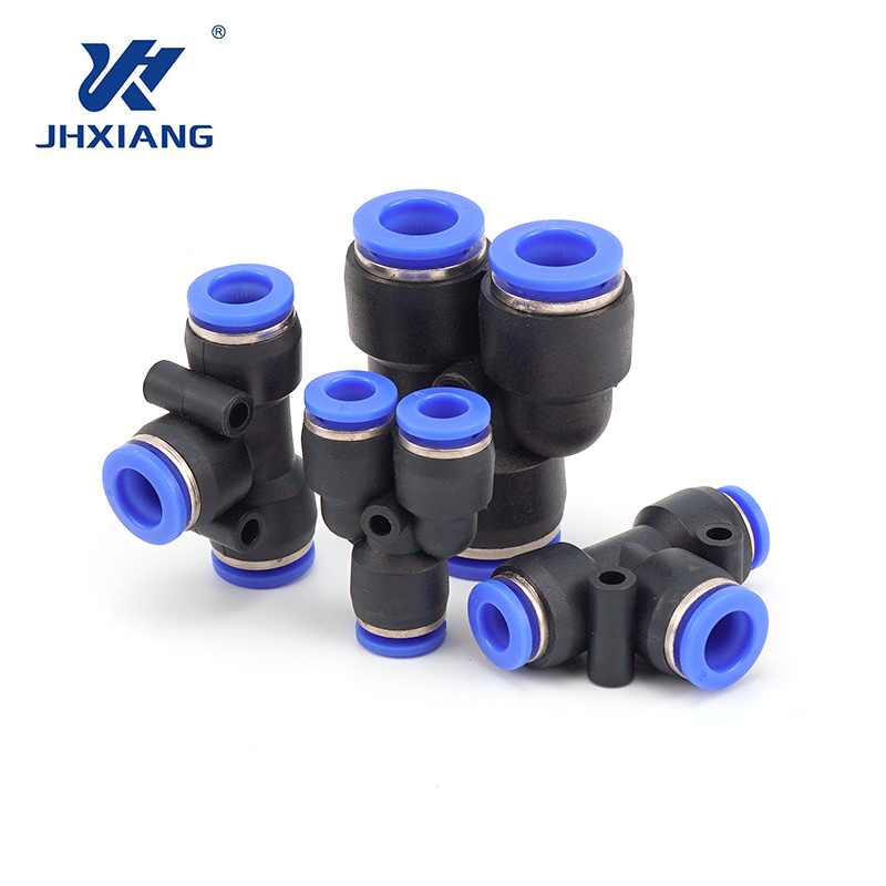
The physical environment destroys air systems faster than pressure ever will. You must select materials that can survive ambient chemicals, temperature extremes, and physical impacts.
Engineers widely use Polybutylene terephthalate (PBT), polyacetal (POM), and various fluoropolymers. These plastics offer excellent chemical washdown compatibility. They resist many industrial solvents and cleaning agents. They also provide significant weight reduction. This is highly beneficial for end-of-arm tooling on high-speed robots.
Specify plastic components for packaging lines and light automation. However, you must understand the implementation risks. Plastics have lower temperature and pressure thresholds compared to metals. They also face UV degradation risks if exposed to direct sunlight for extended periods. They become brittle and shatter under pressure. Always consult the manufacturer's derating curve to understand how elevated ambient temperatures reduce the maximum allowable working pressure.
Brass is the traditional industry standard for general pneumatics. It offers excellent machinability and standard industrial durability. It provides moderate corrosion resistance in typical indoor environments. Bare brass works well for dry, indoor air systems.
Nickel-plated brass adds a hard, protective outer layer. This plating significantly increases corrosion resistance. More importantly, it provides excellent spatter resistance. In welding environments, hot metal spatter melts right through plastic. It bounces harmlessly off nickel-plated brass. Evaluate your environment to determine if the extra cost of nickel plating is necessary for your specific production lines.
Stainless steel provides maximum chemical and thermal resistance. Grade 304 handles most corrosive environments. Grade 316 contains molybdenum, which specifically resists chloride and salt corrosion. You must evaluate the high upfront cost against your operational necessities.
Stainless steel is mandatory for food-grade (FDA) compliance. You cannot use brass or standard plastics in direct food contact zones. Pharmaceutical cleanrooms also require stainless steel to withstand harsh sterilization chemicals. Extreme offshore marine environments demand 316 stainless to survive constant saltwater exposure.
Material | Temperature Range | Chemical Resistance | Best Use Case |
|---|---|---|---|
PBT / POM Plastic | 32°F to 140°F | Moderate | Light automation, robotics |
Bare Brass | -4°F to 175°F | Low | General indoor pneumatics |
Nickel-Plated Brass | -4°F to 175°F | Moderate to High | Welding cells, washdown areas |
316 Stainless Steel | -4°F to 300°F+ | Very High | Food processing, marine, chemical |
Modern machines pack more components into smaller spaces. Control cabinets are crowded. Robotic arms have limited clearance. You must design your air routing to fit these physical constraints without choking system airflow.
When clearance is minimal, standard hex-body connectors fail. You simply cannot fit a wrench around them. Manufacturers solve this by reducing the external footprint. They use internal hex designs. You install these using an Allen key inserted directly through the center of the fitting.
These components are perfect for cramped manifolds. However, you must assess the trade-offs. To make the body smaller, manufacturers often reduce the internal flow diameter. This increases your Delta P. Additionally, manual disconnection becomes difficult. If you cannot reach the release collar with your fingers, maintenance slows down significantly. Always verify the flow coefficient (Cv) before specifying reduced-footprint hardware for high-demand cylinders.
Dynamic machine parts cause tubing to bend and twist. Fixed elbows force the tubing to absorb this twisting motion. Eventually, the tubing kinks or snaps. Swivel elbows solve this problem. They feature a 360-degree rotational body mounted on a threaded base.
As the machine moves, the fitting rotates. The tubing remains relaxed. This eliminates kinking. However, you must mitigate specific risks. Standard swivels are designed for positioning during installation and occasional slow movement. They are not designed for continuous high-speed rotary applications. If you spin a standard swivel continuously, the internal O-ring will melt from friction. For continuous rotation, you must specify dedicated rotary joints.
Upgrading or repairing older pneumatic systems introduces severe compatibility risks. Mixing different thread standards or tubing sizes leads to immediate failures. You must accurately identify existing hardware before ordering replacements.
Thread identification is your first hurdle. National Pipe Tapered (NPT) is standard in North America. British Standard Pipe Tapered (BSPT) is common in Asia and older European equipment. British Standard Pipe Parallel (BSPP) uses straight threads and an external O-ring.
NPT and BSPT look nearly identical to the naked eye. However, their thread angles and pitches differ. NPT uses a 60-degree angle. BSPT uses a 55-degree angle. A 1/4-inch NPT thread has 18 threads per inch (TPI). A 1/4-inch BSPT thread has 19 TPI. You must use a mechanical thread pitch gauge to distinguish between them. Forcing an NPT male thread into a BSPT female port causes cross-threading. This destroys the port, causes micro-leaks, and leads to thread galling.
Tubing mismatch is equally dangerous. Metric and imperial sizes often look similar but do not mix. A 1/4-inch tube measures 6.35mm. A 6mm tube is slightly smaller. If you insert a 6mm tube into a 1/4-inch receptacle, the grab ring barely engages. It will blow out under pressure. If you force a 1/4-inch tube into a 6mm receptacle, you will crush the internal O-ring and damage the claw.
Installation technique matters just as much as component selection. Tube preparation is critical. You must execute perfectly square cuts. Use a dedicated polyurethane tube cutter. Never use scissors or wire snips. Scissors crush the tube into an oval shape. Oval tubing will not seal against a perfectly round internal O-ring. Furthermore, you must deburr rigid tubing edges. Jagged edges will lacerate the internal elastomeric seal during insertion.
Measure the required tubing length, allowing enough slack for machine movement.
Cut the tubing at a perfect 90-degree angle using a specialized blade cutter.
Inspect the cut end for ovality, burrs, or deep scratches.
Push the tubing firmly into the receptacle until it bottoms out against the internal tube stop.
Pull back gently on the tubing to ensure the grab ring teeth have fully engaged.
Routing guidelines prevent side-load stress. Tubing must enter the receptacle perfectly straight. Every tube has a minimum bend radius. If you bend the tube too sharply right after the connection point, you induce asymmetric pressure. The tube pushes hard against one side of the internal seal. It pulls away from the opposite side. Air escapes through the gap. Always respect the manufacturer's minimum bend radius specifications.
Managing a facility with dozens of different connection styles creates operational chaos. Technicians waste time searching for the right adapters. Inventory rooms overflow with redundant parts. You must implement strict procurement criteria to streamline operations.
Evaluate when it is financially viable to specify premium materials. Standard brass components cost less upfront. However, if you install them in a corrosive washdown environment, they will fail rapidly. The labor cost of dispatching a technician to replace a failed brass elbow far exceeds the initial price difference of a stainless steel alternative. Specify materials based on the expected lifecycle of the machine and the severity of the operating environment.
The greatest operational benefit comes from standardizing on a single manufacturer's ecosystem. Pick one connection type and stick with it across all non-specialty machines. When you mix brands, you introduce tolerance stacking. Manufacturer A might produce tubing on the absolute lowest end of the acceptable diameter tolerance. Manufacturer B might produce receptacles on the highest end of the tolerance. When you combine them, the connection is loose.
Staying within one ecosystem ensures exact tolerance matching between the tubing outer diameter (OD) and the fitting receptacle. This drastically reduces technician error during retrofits. It also simplifies your maintenance inventory. You only need to stock one specific style of 8mm elbow, rather than three different variations from three different brands. Standardization keeps machines running and reduces the time required for emergency repairs.
The reliability of a pneumatic system is directly proportional to your engineering choices. You must align the internal mechanism, the material composition, and the environmental realities of the application. Ignoring any of these three factors guarantees eventual system failure.
Base your final procurement decisions on a strict hierarchy of needs. First, filter your options by maximum operating pressure and temperature. Second, evaluate the chemical and environmental exposure. Third, narrow down the choices based on spatial constraints and maintenance requirements. This logical progression ensures you never specify a component that cannot survive its environment.
Audit existing system failure points and document recurring leak zones across your facility.
Utilize digital calipers and thread pitch gauges to accurately identify all legacy components before ordering replacements.
Consult manufacturer technical data sheets to verify exact flow curves and pressure drop ratings for compact designs.
Request material samples for compatibility testing if you operate in harsh chemical washdown environments.
A: Most standard industrial push-in connectors handle up to 150 PSI safely. This rating depends heavily on the tubing material and ambient temperature. Always check the manufacturer's specific pressure-temperature curve. High heat significantly reduces the pressure capacity of plastic components.
A: While technically possible if the sizes match exactly, we strongly advise against it. Mixing brands introduces tolerance stacking. One brand's tubing might be slightly undersized, while another's receptacle is slightly oversized. This mismatch causes micro-leaks and increases the risk of unexpected blowouts.
A: Leaks usually occur due to poor tube preparation or side-loading. If you cut the tube at an angle, it will not seat properly against the internal O-ring. If the tube bends sharply right out of the port, it pulls away from the seal. Scratched tubing also bypasses the O-ring.
A: Both are tapered threads designed to seal through deformation, but their geometries differ. NPT has a 60-degree thread angle, common in North America. BSPT has a 55-degree angle, common in Asia and Europe. They are not compatible. Forcing them together causes severe thread damage.
A: You must use digital calipers to measure the outer diameter of the tubing or the inner diameter of the receptacle. A 1/4-inch tube measures exactly 6.35mm. A 6mm tube is noticeably smaller. Never guess visually, as inserting a 6mm tube into a 1/4-inch port causes blowouts.
A: Push-in types can be reused multiple times. However, you should trim off the scratched end of the tubing before reinserting it to ensure a fresh seal. Compression styles generally require a new ferrule once the original is crushed onto the tubing.


