

close
Choose Your Site
Global
Social Media


Views: 0 Author: Site Editor Publish Time: 2026-08-10 Origin: Site


Improper pneumatic sizing carries hidden operational costs that quietly drain facility efficiency. Oversizing an air cylinder drains compressor energy and inflates component footprints. Undersizing causes sluggish cycle times, stalled loads, and premature equipment failure. Engineering and maintenance teams often rely on guesswork or maximum compressor ratings rather than calculating the true dynamic load, point-of-use pressure, and necessary flow rates. This approach leads directly to inefficient automation systems and frequent downtime.
You need a systematic, physics-based framework for calculating required force and analyzing load dynamics. Matching the exact actuator profile to your application's spatial, environmental, and precision constraints prevents costly redesigns. This guide breaks down the technical formulas and mechanical realities required to size pneumatic actuators correctly the first time.
Force Margin is Non-Negotiable: Sizing exactly to the static load guarantees failure; a 25% to 100% force margin is required to overcome dynamic friction, breakaway friction, and achieve target speeds.
Pressure Reality Check: Bore size must be calculated based on the minimum available pressure at the point of use, accounting for line drops, not the compressor’s maximum rating.
Actuation Type Matters: Choosing between single-acting (spring return) and double-acting cylinders fundamentally alters force calculations and air consumption.
Profile Dictates Performance: Selecting between standard, compact, and guided cylinders depends entirely on spatial constraints, stroke length, and the presence of lateral forces (side loading).
System-Wide Sizing: An accurately sized cylinder will still underperform if the directional control valve (Cv rating) or tubing restricts the required airflow.
The physical weight of an object rarely equals the actual force required to move it. Static load refers to the mass of the object at rest. Dynamic load accounts for the resistance encountered during motion. You must calculate the coefficient of friction based on the sliding surface. Moving a 500-pound steel billet across a flat steel plate generates massive friction. You need to know exactly how much resistance that surface creates before selecting a bore size.
The load's angle also dictates the total force requirement. Horizontal movements only fight friction. Vertical movements must lift the entire dead weight plus overcome internal seal friction. Inclined movements require calculating the gravitational vector force alongside the frictional resistance. Ignoring these dynamic variables guarantees an undersized actuator.
Sliding Surface Material | Estimated Coefficient of Friction (µ) | Force Required to Move 100 lbs (Horizontal) |
|---|---|---|
Steel on Steel (Unlubricated) | 0.58 | 58 lbs |
Steel on Bronze (Lubricated) | 0.15 | 15 lbs |
UHMW Plastic on Steel | 0.12 | 12 lbs |
Profiled Linear Bearings | 0.01 | 1 lb |
Using the compressor room's maximum PSI for cylinder calculations is a common engineering failure point. A rotary screw compressor might generate 120 PSI at the tank, but that pressure degrades rapidly as it travels through the facility piping. You must account for pressure drops across directional control valves, fittings, filters, regulators, lubricators (FRLs), and long tubing runs. Every 90-degree elbow joint and meter of polyurethane tubing reduces the available kinetic energy.
Point-of-use pressure often drops to 80 PSI or lower during peak facility demand. You must establish a strict rule of calculating bore size based on the lowest anticipated pressure at the machine level. If you size a cylinder assuming 100 PSI and the line pressure drops to 75 PSI when adjacent machines cycle, your actuator will stall mid-stroke. Always measure pressure directly at the valve manifold feeding the cylinder to establish an accurate baseline for your calculations.
Double-acting cylinders use compressed air to drive both the extension and retraction strokes. This design provides maximum control and consistent force in both directions. It remains the standard choice for most industrial automation applications. You can regulate the speed of each stroke independently using meter-out flow control valves on both cylinder ports.
Single-acting cylinders use compressed air for one stroke and an internal mechanical spring for the return stroke. These units impact your force calculations significantly. Single-acting cylinders require additional force to overcome the internal spring resistance during the work stroke. The spring consumes roughly 10% to 20% of the cylinder's total theoretical force output. You must deduct this spring resistance from your final force calculations.
Specify single-acting cylinders only when your application meets these specific criteria:
The application requires a fail-safe return to a home position if facility power or air pressure is lost.
The work is only performed in one direction, such as pressing a bearing or clamping a workpiece.
The required stroke length is relatively short, typically under six inches, due to internal spring limitations.
Conserving compressed air on the return stroke is a strict facility requirement.
Pneumatic sizing relies on a fundamental fluid power equation: Force (F) = Pressure (P) x Area (A). Pressure represents the available air pressure at the cylinder port. Area represents the surface area of the internal piston. To find the required bore size, you rearrange the formula to A = F / P. Once you have the required area, you calculate the bore diameter using the standard geometric formula for the area of a circle.
You must understand the critical difference between extension force and retraction force. During the extension stroke, compressed air pushes against the entire surface area of the piston. During the retraction stroke, the piston rod occupies a portion of the internal chamber. The compressed air can only push against the remaining annular area. Therefore, the "pull" force is always lower than the "push" force. If your application requires heavy pulling, you must size the bore based on the reduced retraction area.
Bore Size (mm) | Rod Diameter (mm) | Extension Force at 80 PSI (lbs) | Retraction Force at 80 PSI (lbs) |
|---|---|---|---|
32 | 12 | 99 | 85 |
40 | 16 | 155 | 131 |
50 | 20 | 243 | 204 |
63 | 20 | 386 | 347 |
Sizing a cylinder to match the exact calculated load guarantees sluggish performance. You need excess force to accelerate the mass and overcome breakaway friction. Breakaway friction is the initial spike in resistance that occurs when static seals break their bond with the cylinder barrel. Industry-standard multipliers dictate the required force margin based on target speeds. You cannot achieve rapid cycle times without a substantial surplus of pneumatic energy.
For slow, steady movements, specify a 25% to 30% additional force margin. This ensures smooth actuation without jerky starts. For high-speed or high-impact applications, specify a 50% to 100% additional force margin. Fast automation requires rapid acceleration. A cylinder sized with a 100% margin will reach its target velocity in a fraction of a second. If you neglect these multipliers, the cylinder will eventually complete its stroke, but it will fail to meet your machine's cycle time requirements.
Match the stroke length exactly to the required travel distance. Allowing the internal piston to bottom out destructively against the end caps causes rapid mechanical failure. If the stroke is slightly longer than the required travel, use external hard stops to absorb the impact. For long-stroke applications, you must calculate column strength to prevent rod buckling. A long, thin piston rod will bend under heavy compressive loads. You may need to upsize the rod diameter, specify a stop tube, or select a larger bore cylinder simply to gain a thicker, stiffer rod.
Achieving the calculated cycle speed requires matching the cylinder's internal volume to a directional control valve with an adequate flow coefficient (Cv) rating. The Cv rating defines how much air can pass through the valve in a given time. Connecting a large-bore cylinder to a valve with a low Cv rating chokes the airflow. The cylinder will move slowly regardless of the available system pressure. You must size the valve, the tubing, and the fittings to handle the peak flow rate required for your target speed.
The SC standard pneumatic cylinder represents the workhorse of general automation. These units excel in heavy-duty pushing, pulling, and applications requiring long stroke lengths. They feature robust tie-rod construction that withstands harsh industrial environments. You will find them deployed in packaging machinery, material handling systems, and automotive assembly lines where durability takes precedence over space savings.
This profile offers the widest range of bore sizes and mounting accessories. Many standard cylinders comply with ISO 15552 or VDMA 24562 standards. This ensures easy interchangeability across different manufacturers without modifying machine brackets. However, standard cylinders require significant installation space. Their bulky profile and extended end caps make them unsuitable for tight machinery footprints. They also consume higher air volumes per cycle compared to compact alternatives.
When spatial constraints dictate the machine design, the SDA mini compact cylinder provides the necessary actuation. These units are engineered for tight spaces, short-stroke clamping, pressing, or holding applications. The extruded aluminum body features a low-profile design that allows integration into dense machinery footprints where standard tie-rod cylinders simply cannot fit.
Compact cylinders often feature internal threads and flush mounting holes, eliminating the need for bulky external brackets. The primary trade-off involves stroke length limitations. Compact cylinders rarely exceed a few inches of travel. Furthermore, their short internal bearing surfaces make them highly sensitive to side loading. If the load is not perfectly aligned with the rod trajectory, the rod will bend and the internal seals will fail rapidly.
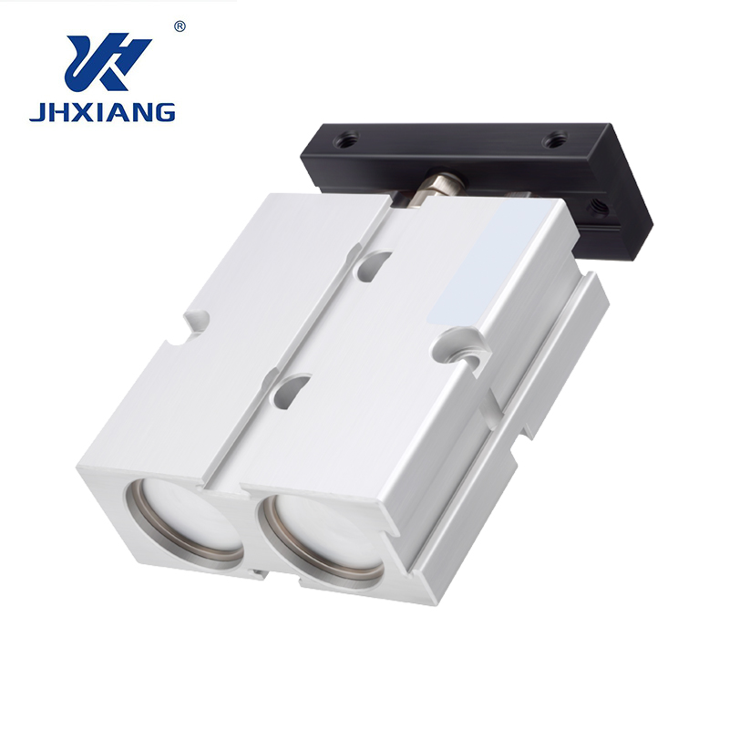
Applications requiring high precision, anti-rotation capabilities, and resistance to lateral forces demand specialized hardware. The TN dual axis air cylinder integrates two parallel piston rods connected by a rigid guide plate. This built-in guidance system absorbs side loads directly, protecting the main piston seals from uneven wear.
The dual-rod design ensures a precise linear trajectory without requiring external guide rails or linear bearings. This simplifies machine design and reduces overall assembly time. The rigid guide plate prevents the load from rotating during the stroke, which is mandatory for pick-and-place operations or precision stamping. The trade-offs include a higher initial procurement cost and a heavier physical footprint compared to standard single-rod cylinders.
Evaluate your application's tolerance for rod rotation. Standard round rods will rotate slightly as they extend and retract due to internal machining tolerances. If your application requires strict orientation—such as pressing a square peg into a square hole—you must utilize guided cylinders or non-rotating rod designs. Non-rotating cylinders use hexagonal rods or internal guide pins to maintain strict alignment throughout the stroke.
Repeatable end-of-stroke positioning relies on external sensors. Most modern cylinders feature magnetic pistons. You can mount reed switches or solid-state sensors directly to the cylinder body. These sensors detect the magnetic field of the piston and send a signal to the PLC when the cylinder reaches its fully extended or retracted position. Solid-state switches offer higher reliability and faster response times for high-cycle automation compared to mechanical reed switches, which rely on fragile internal contacts.
Oversizing a cylinder wastes compressed air, which is one of the most expensive utilities in a manufacturing facility. Calculate the wasted CFM (Cubic Feet per Minute) over a year of continuous operation. Increasing a bore size from 2 inches to 3 inches more than doubles the internal volume. If that extra force is unnecessary, you are paying to compress air that performs no useful work.
Optimize bore size to match the required load precisely, keeping the necessary speed margins intact. You can also utilize dual-pressure systems to reduce compressor load. Many applications require high force to extend (clamping or pressing) but minimal force to retract. By supplying 80 PSI for the work stroke and regulating the return stroke down to 30 PSI, you drastically reduce the total air volume consumed per cycle.
Matching the cylinder material to the operating environment prevents premature corrosion and mechanical failure. Standard automation environments utilize aluminum bodies and end caps. Aluminum provides an excellent strength-to-weight ratio and dissipates heat effectively. Corrosive environments, chemical processing, and food-grade washdown zones require stainless steel bodies. Stainless steel resists harsh cleaning chemicals and prevents rust contamination.
Seal material selection dictates the cylinder's lifespan under specific conditions. Evaluate your application against these common seal compounds:
Seal Material | Primary Characteristics | Best Application Environments |
|---|---|---|
Nitrile (Buna-N) | Standard temperature range, good wear resistance. | General industrial automation, standard factory floors. |
Viton (FKM) | High heat resistance, excellent chemical compatibility. | High-temperature zones, chemical processing, automotive welding. |
Polyurethane | Exceptional abrasion resistance, high durability. | High-cycle applications, heavy dust environments, rapid actuation. |
Standard single-rod cylinders are designed exclusively for axial loads. They push and pull in a straight line. They fail rapidly under lateral stress. Side loading occurs when a force pushes perpendicular to the piston rod. This forces the rod against the internal bearing, causing uneven seal wear, scored cylinder barrels, and eventually, a bent rod. Even a side load of 5% of the total axial force can destroy a standard cylinder within weeks.
You must mandate the use of external linear guides to support heavy or off-center loads. The cylinder should only provide the linear pushing force, while the external rails absorb the lateral weight. When external guides are not feasible due to space constraints, specify guided cylinders or dual-axis configurations. These specialized units contain heavy-duty internal bearings designed specifically to handle lateral forces without compromising the pneumatic seals.
Selecting the wrong mounting hardware guarantees mechanical binding. Evaluate rigid mounts versus pivot mounts based entirely on the load's trajectory. Rigid mounts lock the cylinder body in place. They are strictly for loads that move in a perfectly straight line on external rails.
If the load moves in an arc—such as opening a heavy trap door or actuating a lever—you must use pivot mounts. Clevis or trunnion mounts allow the cylinder body to pivot as the rod extends, maintaining perfect alignment with the load's changing angle. Rigidly mounting a cylinder to a load that moves in an arc will cause immediate rod bending, severe binding, and catastrophic seal failure on the very first cycle.
Mounting Style | Type | Best Use Case |
|---|---|---|
Front/Rear Flange | Rigid | Straight-line pushing or pulling where the cylinder body must remain stationary. |
Foot Mount | Rigid | Mounting parallel to the machine base for straight-line horizontal loads. |
Rear Clevis | Pivot | Loads that travel in an arc. Allows the cylinder to swing during actuation. |
Center Trunnion | Pivot | Heavy loads moving in an arc. Balances the cylinder weight and reduces bearing stress. |
A moving load generates kinetic energy. When the cylinder reaches the end of its stroke, that kinetic energy must be absorbed. If the piston slams into the end cap at high speed, the impact will fracture the cylinder body or shear the mounting bolts. You must analyze the kinetic energy based on the mass of the load and the velocity of the stroke.
Compare your mitigation options carefully. Mechanical elastomer bumpers are suitable for light loads and slow speeds. They provide basic shock absorption. Adjustable pneumatic cushions trap a small volume of air at the end of the stroke, creating a decelerating air spring. These are ideal for medium loads. For high-speed or high-mass loads, you must install external industrial shock absorbers. External shocks absorb massive kinetic energy, allowing the cylinder to operate at maximum speed without self-destruction.
Utilize pneumatic sizing software to validate dynamic load calculations and required flow rates before purchasing hardware.
Consult manufacturer flow charts to match the directional control valve Cv rating exactly with your selected bore size and target speed.
Contact an application engineer to verify column strength calculations for any stroke length exceeding 24 inches to prevent rod buckling.
Audit your facility's point-of-use air pressure at the specific machine manifold to establish an accurate baseline for your force formulas.
A: First, determine the total force required to move the dynamic load, including friction. Add a 25% to 100% force margin for speed. Divide this total required force by the minimum available air pressure at the point of use. This gives you the required piston area. Use the area of a circle formula to find the bore diameter.
A: Extension force is generated when air pushes against the entire surface area of the piston. Retraction force is lower because the piston rod occupies space inside the cylinder, reducing the effective surface area the air can push against. Always calculate pull applications based on this reduced annular area.
A: Slow movement is usually caused by restricted airflow, not a lack of pressure. Check the directional control valve's Cv rating to ensure it can deliver the required volume of air. Undersized tubing, clogged exhaust mufflers, or incorrectly adjusted flow control valves will also choke the cylinder speed.
A: Choose a compact cylinder when machinery space is severely limited and the required stroke length is short. They are ideal for clamping and pressing in tight footprints. Avoid them if your application involves long travel distances or unsupported lateral loads.
A: Prevent rod bending by calculating the column strength of the piston rod under maximum compressive load. If the load exceeds the rod's buckling limit, you must specify a cylinder with a larger rod diameter, use external linear guide rails to support the weight, or install a stop tube.
A: No. Standard single-rod cylinders are designed strictly for axial loads. Lateral forces will quickly score the cylinder barrel and destroy the internal seals. You must support lateral loads with external linear bearings or specify guided dual-axis cylinders built to absorb side impacts.


